looks like a real dog, acts like a real dog (well almost!!)
2020 / Class Project
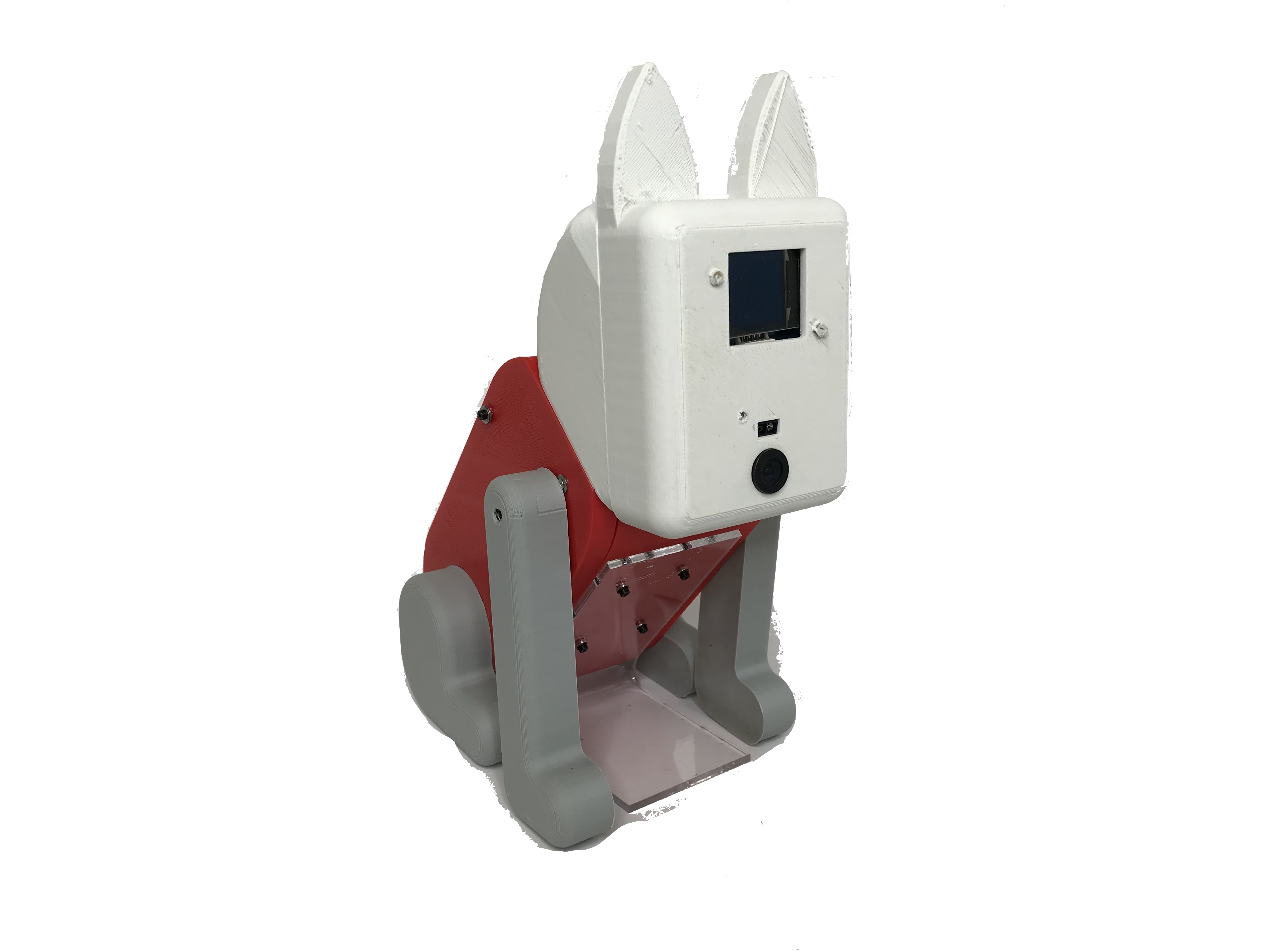
RoboDog is a revolutionary educational toy for young users who want to embark on a journey of owning a real dog. It is a great first pet to have to hone your skills as a pet owner. You can teach RoboDog tricks with different bones and be amused by his skills – and yours too. In few simple steps you can teach your favorite pet to pose and play with it to have endless fun.
RoboDog was built for the Educational Robotics class. Our goal was to design a system to help children learn a powerful idea in Artificial Intelligence and Machine Learning. We chose to teach the concept of TRAINING by engaging our users in an activity of training a dog. We hoped the users would understand the need of data and training in AI and Machine Learning and how the system responds based on the type of data provided.
Our goal was to make the puppy respond when shown different treats (different colors).

How Does It Work?
The steps to train the RoboDog are simple, by design. Here are the steps
- Show the dog Train Block (in the figure below) to put it in a training mode.
- Move the front legs to different position of choice.
- Show the bone to the dog, until the dog notices and acknowledges that it has seen the bone.
- Repeat the steps 2 and 3 for different positions and colors.
- Show the dog Run Block (in the figure below) to put it run mode.
- Now show the dog the bones you trained (and you didn’t) to play with it

Here is a demo:
How it’s made?
(Contact the author for the link to the parts )
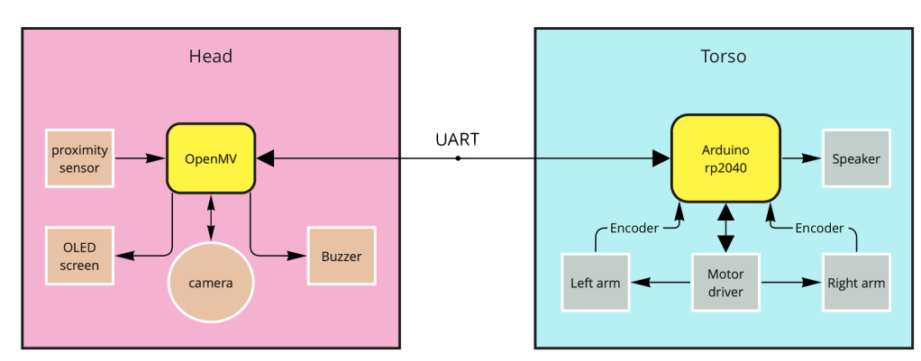
The puppy has two microcontrollers inside: an Arduino RP2040 and an OpenMV camera module. The functions of the head – cute little eyes, beep to give feedback to the users, proximity sensor to detect if the user is trying to feed the dog as well as the camera that sees the bone and identifies the color- are all carried out by the OpenMV camera module.
The torso includes motors, encoders and a speaker and they are controlled by the Arduino RP2040 microcontroller. The two microcontrollers talk using UART protocol.
But seriously, how does it work?
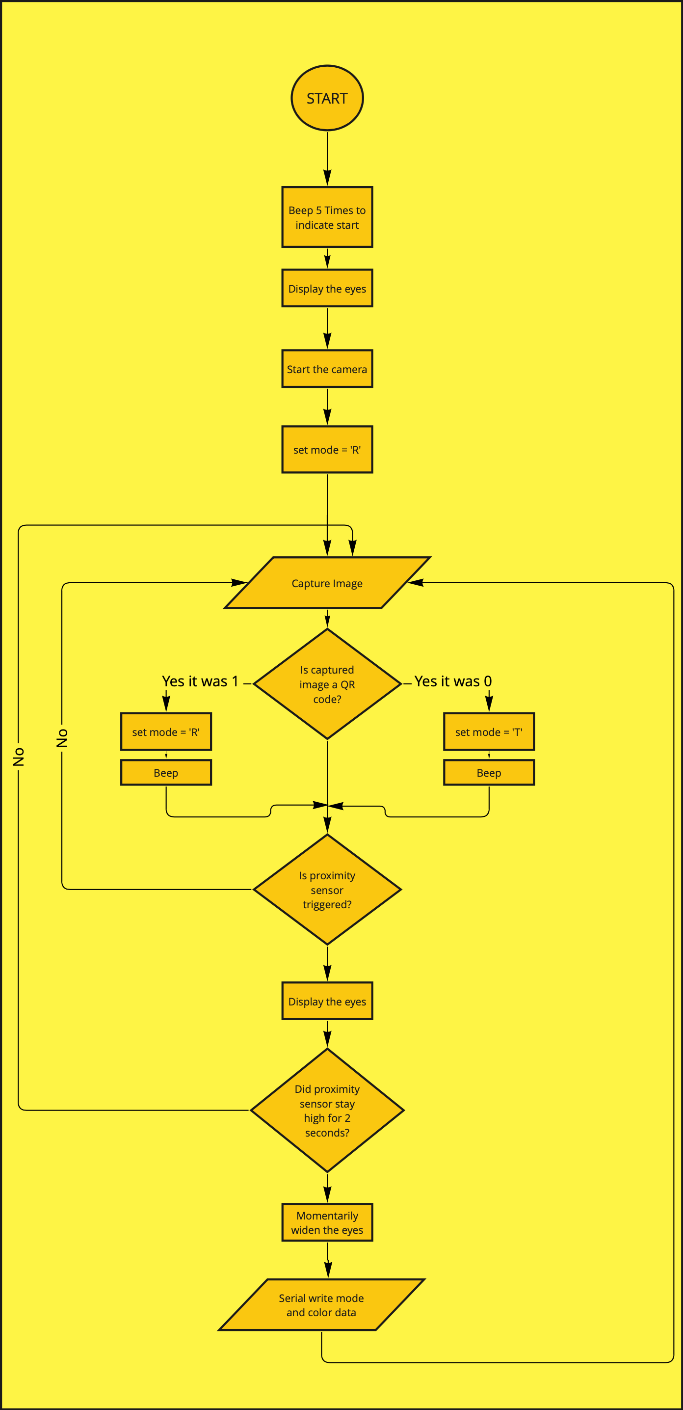
It all starts with the head. As soon as the camera boots up the eyes are drawn on the OLED screen. The camera is always looking for QR codes and ready to change states – Train or Run. If the proximity sensor is triggered it means something is close to the nose (mouth or camera) and the dog responds by looking downwards. To give users time to stabilize the bone, the camera takes an image after two seconds, and the eyes go bigger to inform the user that data is taken. The color data from the camera comes from a small ROI in the center to make sure the data is coming from only one source.
The data is taken in LAB color format – more about LAB here. In short, L is the light intensity level, a is the value of Green-Magenta level and B is the value of Yellow-Blue level in the image. By using LAB color space and ignoring the L value it was possible to reduce the color into 2D.
Every time the proximity sensor is triggered and stays high for 2 seconds the camera captures mid A and B values from ROI and passes the value to the Arduino RP2040 along with the mode (default mode value is R for Run and the other possible value is T for Train – changed by showing the QR codes). The OpenMV sends data to Arduino RP2040 in a JSON string in a format shown below – where T stands for Train, 10 and 25 are a and b value respectively.
{
“mode”: “T”,
“a”: 10,
“b”: 25
}
The mode value changes from T to R when Run Block is shown to the camera.
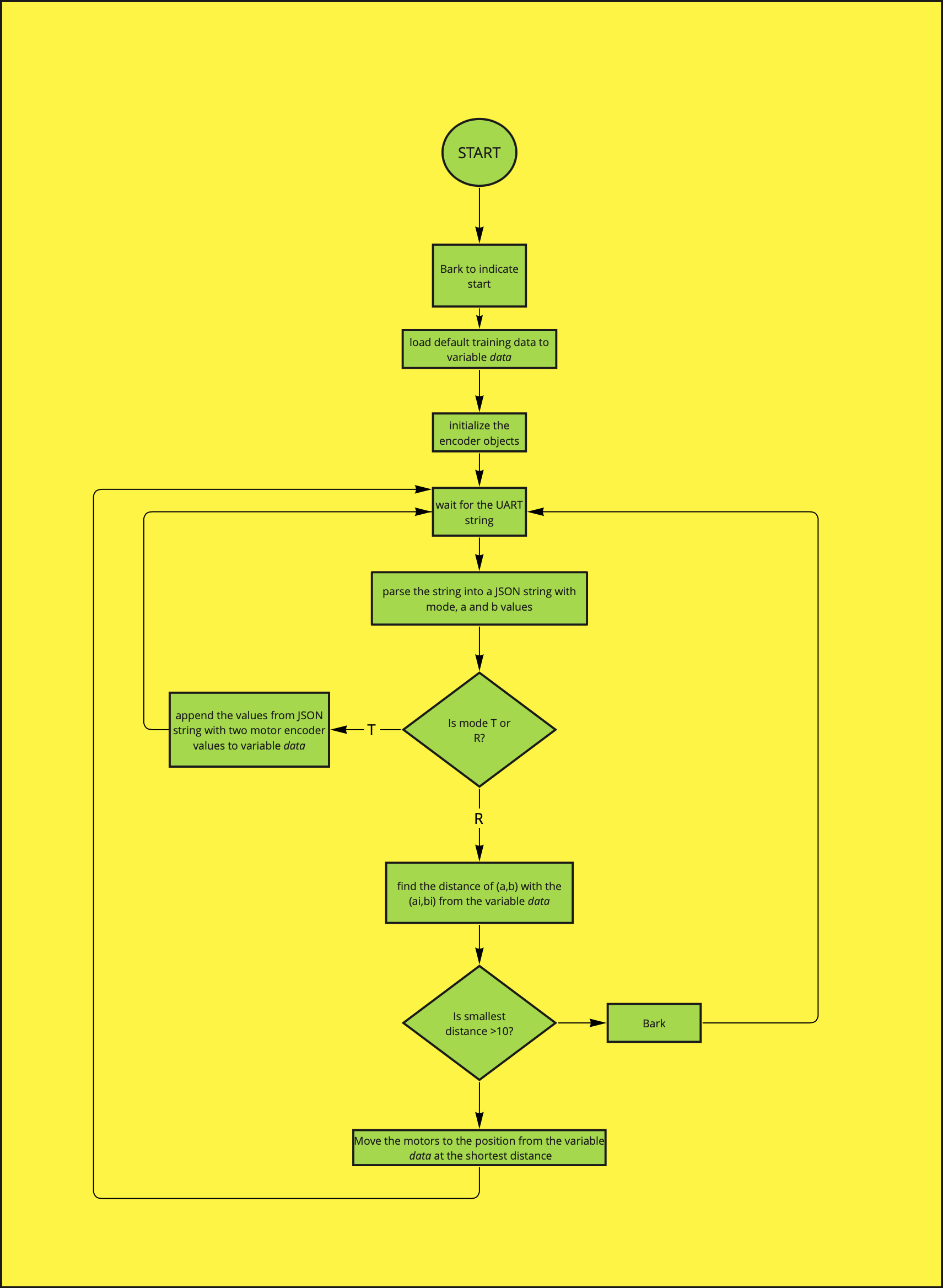
On the Arduino side, the Arduino is always waiting for the UART data from OpenMV. As soon as the data is received the json string is parsed into mode, a and b values. If the mode is T for Train then the Arduino appends motor position data along with the color data into an array. The format of the array is shown below
data= [[a,b,left_motor_position, right_motor_position][…]]
It keeps appending the data for as long as the parsed mode value is T.
If the user shows the Run Block to the camera the mode on OpenMV changes to R for Run and it sends R as mode value to the Arduino. In this mode, the Arduino takes the a and b values and compares it will all the other a and b values in the data array. The smallest distance between the new a and b values and the data stored in the array is calculated and the motor positions for the closest a and b values are saved. If the distance is smaller than 10 (an arbitrary value to show that the new color is actually close the saved color) the motors are moved until they reach the defined positions. Otherwise the dog barks, to show that he is confused.
Here are the flowcharts for OpenMV and Arduino codes.
List of items:
| SN | Name of Part | Price | Comments |
|---|---|---|---|
| SN | Name of Part | Price | Comments |
| 1. | Arduino RP2040 | $26.80 | |
| 2. | OpenMV Camera | $65.00 | camera is out of stock |
| 3. | Grove OLED display | $16.40 | |
| 4. | Grove Line Finder | $4.30 | |
| 5. | Grove buzzer | $2.10 | |
| 6. | TT motors with encoders X 2 | $14.80 | |
| 7. | Grove Speakers | $17.10 | |
| 8. | DRV8833 Dual Motor Driver | $8.95 | |
| Total | $155.45 |
